PetLibro reposition button
A one-button wall plug that fixes both cat feeders' schedules at once. Press it, an ESP32 calls the PetLibro cloud, and a light tells you how it went. No hub, no phone.
- Year
- 2026
- Made with
- ESP32-S3, MicroPython, a gutted USB charger, 3D-printed housing
- I did
- Everything: firmware, wiring, enclosure, the API client
- Links
- Source on GitHubFull video
My cats eat from two Polar wet-food feeders. Every night when I refill them, each feeder's schedule has to be repositioned so the next feeding lines up — and in the app, that's several taps deep, per feeder, every single night.
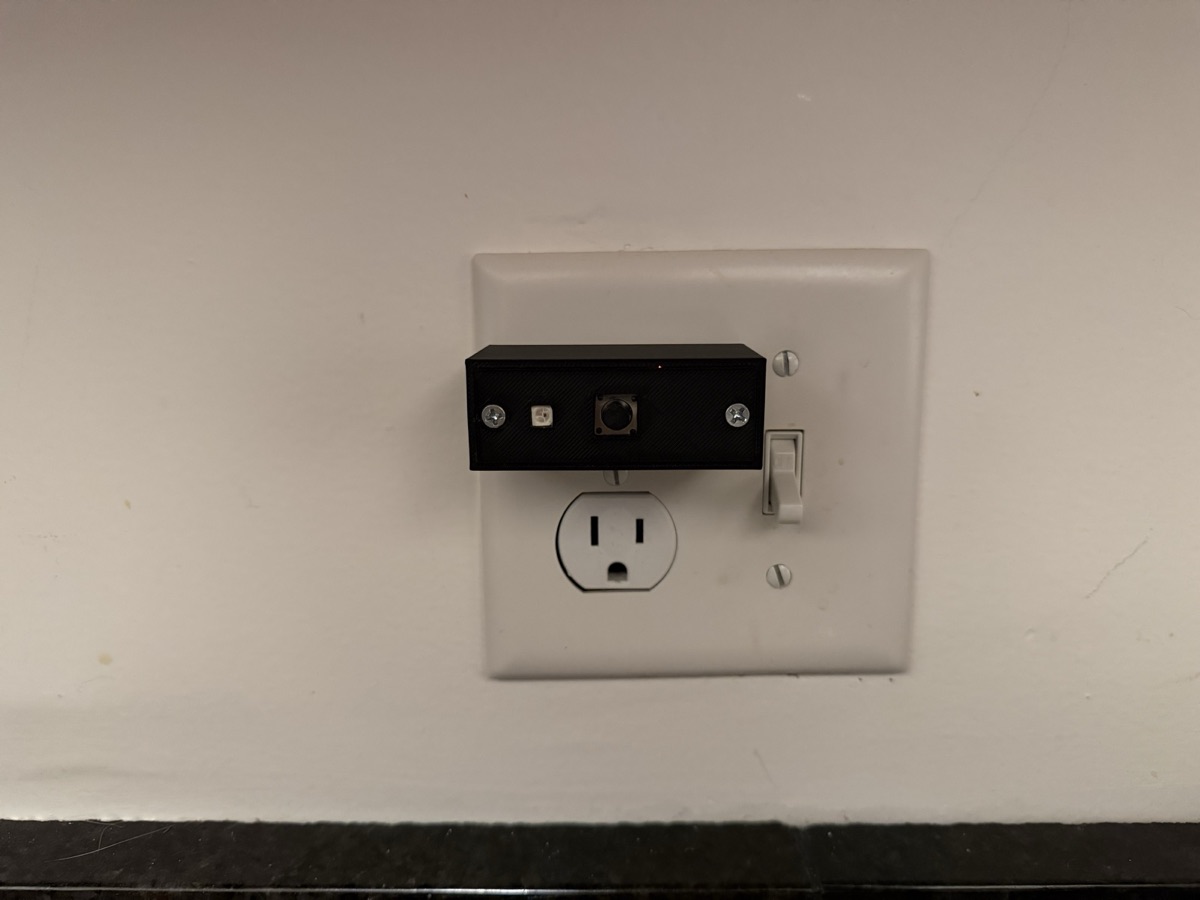
I got tired of it. So now there's a button on the kitchen wall: one press does both feeders, and the light shows how it went.
The protocol comes from the excellent jjjonesjr33/petlibro Home Assistant integration, re-implemented as a ~150-line client that runs unchanged on both CPython and MicroPython. The exact code I test on my desk is the code that ships to the ESP32.
PetLibro only allows one app session per account, so the button gets its own account with the feeders shared to it. Tokens are cached on flash and only refreshed when the API says they've expired.
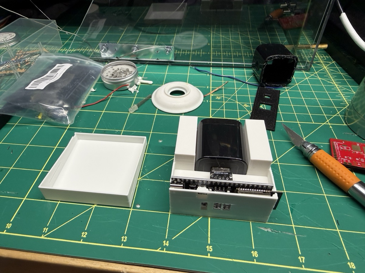
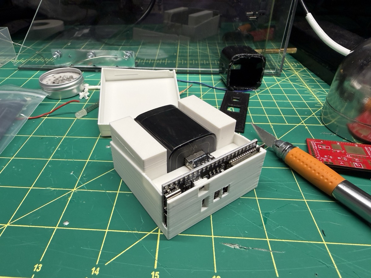
v1: honest and boxy
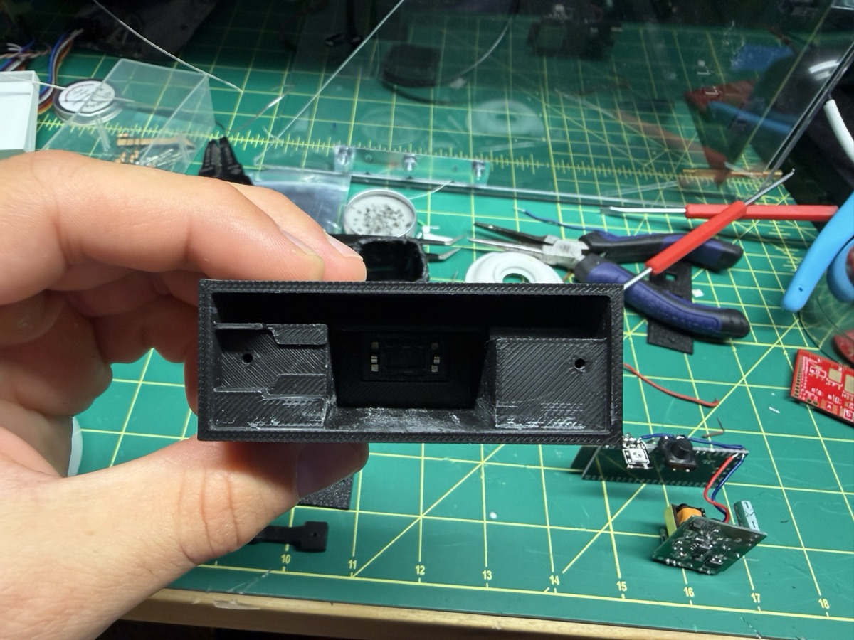
The devkit and an off-the-shelf USB charger side by side in a printed case. It worked. It was also three times bigger than it needed to be.
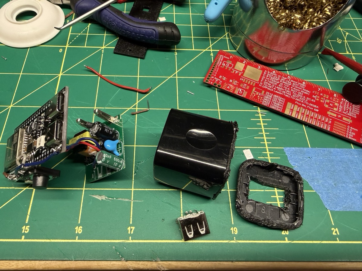
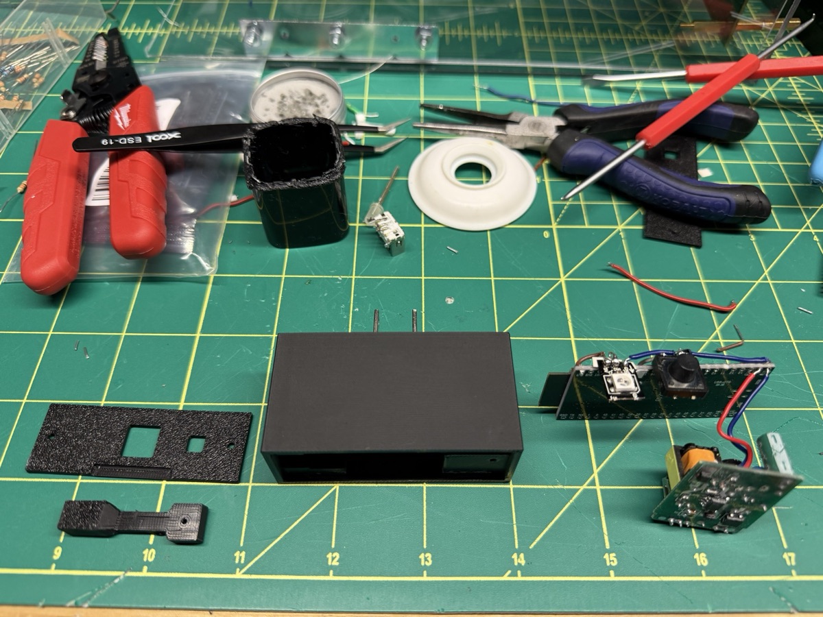
v2: delete the air
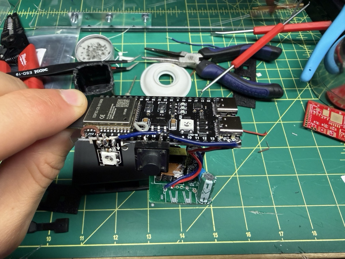
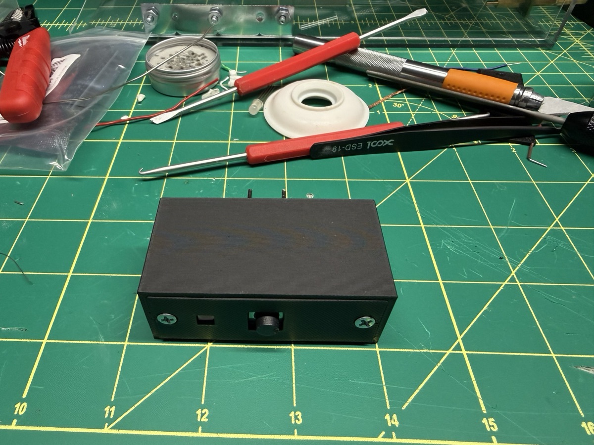
The charger got gutted — shell cut open, USB port desoldered — and its bare PCB now feeds the devkit's 5V pin directly. Everything sandwiches into an outlet-format housing: prongs out the back, button and light through the faceplate, two screws holding it together.
- 1
RGBW is not RGB
Send a 4-die LED 3-byte frames and it doesn't glitch — it stays completely dark.
- 2
Clone boards lie about the 5V pin
Two power faults, each hidden by the other depending on where it was plugged in.
- 3
Run a 5V pixel from 3.3V
The logic threshold drops with it, so no level shifter needed.
- 4
Amp ratings mean nothing to WiFi
A cheap "1A" wall wart browned out the instant the radio fired.
- 5
Give headless devices a flight recorder
A boot log on flash turned "it doesn't work on the wall" into a read-back.
- 6
Simulate before soldering
Wokwi proved the whole button-to-cloud loop before any hardware existed.
Heads up: this carries mains voltage inside a printed enclosure. If you build one, mind creepage around the charger board and insulate the prong connections.